
 Українська (Україна)
  Русский (Россия)
  English (United Kingdom)
 False alarms of stair lighting when using pyroelectric or infrared sensors.
In this article, you'll find information about the operating principles of pyroelectric motion sensors and infrared obstacle sensors that can be used with our controllers. Our controllers already include all filters and necessary hardware solutions for stable operation with all supported sensor types. In 99 cases out of 100, you likely won't need this information and won't encounter any problems. However, sometimes our customers encounter issues caused by incorrect sensor installation location, sensor type, or wiring. Therefore, this article is useful reading during the design and selection phase of automatic stairwell lighting equipment. You'll also learn how to solve these problems in specific cases for each sensor type.
Pyroelectric sensors.
Customers most frequently report false alarms when using pyroelectric sensors. This is quite logical and understandable. The sensor operates by detecting the movement of objects whose temperature is 3-6 degrees Celsius higher than the surrounding background. The sensor has a viewing angle of approximately 150 degrees. Our sensors have a limiting sleeve under the Fresnel lens, which limits the temperature to 30-45 degrees (depending on the model). The response distance is up to 5-7 meters. This means that if the moving object is colder than the background or the temperature difference is less than 5 degrees, the sensor will not trigger. If there is a sun-heated wall behind the sensor, the sensor will also not detect the moving person. If a heating unit or underfloor heating is in the field of view, the sensor may also fail to detect a moving person or generate false alarms, detecting the movement of warm air.
How does the signal to turn on for a pyroelectric sensor work?
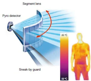
In its idle state, the sensor's signal wire is pulled low (to the negative terminal) via a 22 kOhm resistor. Consequently, the controller input will show a logical zero (0 V - no voltage). When triggered, the sensor's signal contact switches to +3.3 V, which corresponds to a logical high. A high signal (+3.3 V) is sent to the controller input. The controller turns on the backlight, keeping it on for a set timeout (configurable by the user) after the signal returns to zero. If the signal changes during this time, the timer restarts, and shutdown will begin after the time elapses since the last trigger.
Where can a false signal come from?
In fact, there can only be three reasons.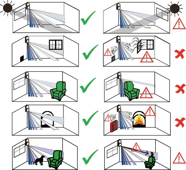
1. There is air movement in the field of view, the temperature of which differs from the background by 3-6 degrees.
This issue may occur if there are heated objects within your sensor's field of view or if the sensor is installed in a position where it detects movement beyond your staircase, as the detection range is 5-7 meters or even more. If relocating the sensor isn't an option, you'll need to choose a different type of sensor, such as an ultrasonic or infrared obstacle sensor.
2. A high signal (logical one) appears in the signal wire, which is perceived by the controller as a signal to turn on.
The user manual for our automatic stair lighting controllers specifies the use of a shielded signal wire, the shield of which must be grounded or at least connected to the power supply housing or grounded. This is no accident. Running any long wire effectively creates an antenna that will "catch" all electromagnetic pulses, especially if the wire from the sensor to the controller is installed in the same cable channel as the power wires for the stair LED strips. The LED strips are always connected to the positive terminal of the power supply, meaning they are always supplied with +12 or +24V, and the negative wire is used to turn them on or off by the controller. Therefore, in addition to the antenna with inductive currents, you may also have a transformer with the signal wire as the secondary winding. In this case, you may encounter quite high voltages. For this reason, we pulled the sensor input negative in the controller itself via a 22 kOhm resistor, and the sensor chip output positive in the sensor via a 10 kOhm resistor, creating a resistance of 12 kOhm during operation and 22 kOhm in standby mode. This pull-up is sufficient for any shielded wires and even for standard twisted-pair cables, provided the wire is routed remotely from any power supply wires. At the same time, it doesn't interfere with connecting other types of sensors to the same input. However, if induced currents in the signal wire exceed the ability of the 22 kOhm resistor to discharge them to ground, the controller will interpret this voltage as a turn-on signal once it reaches at least 1.5 V.
To solve this problem, follow the instructions in the user manual and use shielded wires with a grounded or neutralized shield. But sometimes you discover this too late, when the wires are already installed and finishing work is complete, and there's simply no way to replace the wire. What can you do? There are two options:
- You can use infrared obstacle sensors if the installation location allows. The idea is that infrared sensors, when idle, constantly output a high +5V signal to the controller's signal terminal. When an obstacle is detected, they are pulled to zero, meaning a logical zero is sent to the controller terminal, and the controller initiates activation. This prevents inductive currents in the wires from interfering with the system's operation. The only issue is whether the intended installation location allows it, as these sensors must be installed at a certain height so they don't detect a floor or step and aren't constantly on. Also note that there are Chinese clones of sensors with an inverted output that operate like pyroelectric sensors, meaning their output is logical zero when idle and a high signal (logical one) when triggered. Such sensors are obviously unsuitable.
- You can additionally pull the pyroelectric sensor to ground using a lower-resistance resistor. For this purpose, it's best to use a variable resistor with a value of up to 50 kOhm. The diagram below shows how to do this.
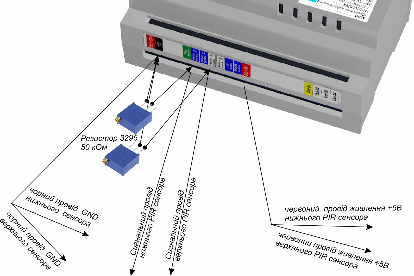
First, set the resistor to its maximum resistance value of 50 kOhm and turn the screw to decrease the resistance until false alarms no longer occur. Typically, these values are around 30-40 kOhm. At values below 20 kOhm, the controller may no longer register the sensor's activation signal. According to the formula for parallel-connected resistors, the total resistance will be equal to or less than 10 kOhm and will be compensated for by the sensor's pull-up to the positive terminal when triggered through the 10 kOhm resistor.
3. The third reason is that the sensor is damaged or faulty. This is easy to check. Simply connect the sensor directly to the controller, without using any wires, directly to the controller terminals. The sensor simply needs to be replaced. The sensors we supply are always tested before sale and are guaranteed to be functional. We provide all our customers with videos of the product inspection and packaging, which are stored on our server for three years, so you can always verify that everything is working properly. If the sensor starts to perform poorly after storage or use in hot and humid environments for several years, the electrolytic capacitors have likely dried out and the sensors need to be replaced.
Infrared obstacle sensor E18-D80NK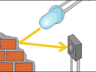
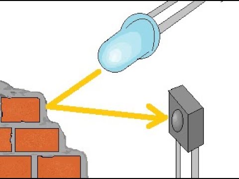
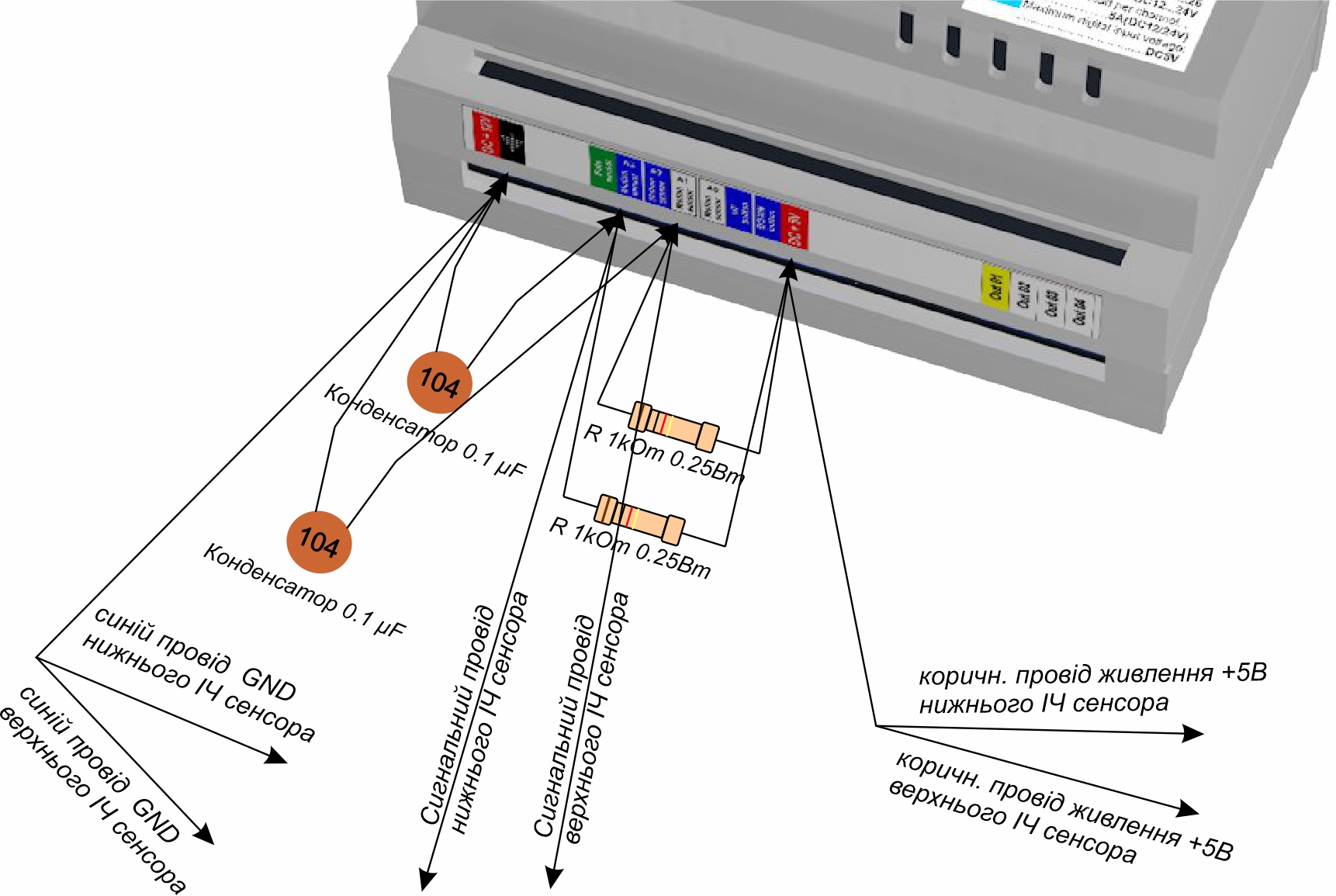
This sensor operates by emitting infrared light and monitoring the reflected beam. It has a trimpot that allows the sensing distance to be adjusted from 3 to 80 cm. When idle, the sensor is connected to the +5V power supply. When an obstacle is detected, the sensor disconnects the power supply, leaving the signal wire suspended in midair. Since the controller input is pulled low, the signal wire is reliably pulled to ground, and a logical zero is detected at the controller input, which triggers the sensor to turn on. As we can see, there's no dependence on inductive currents in the wires, and these sensors operate reliably even with poor-quality wiring. However, the problem arises elsewhere: since the infrared beam is a light beam in the infrared spectrum, it is naturally sensitive to ambient light levels and beam reflection, especially at sensing distances close to the maximum permissible. Avoid installing sensors opposite or near mirrors or glass, as the reflected signal will trigger them. Avoid placing sensors opposite each other, as this will cause them to be triggered continuously. Avoid exposing them to beams from remote controls of other household appliances. When choosing an installation location, keep in mind that the angle of emission and reflection (angle of view) is approximately 30 degrees, so the sensor should not be installed lower than 30-40 cm from the floor or a side step, to prevent the sensor from measuring the distance to them. When selecting wires, consider the DC voltage drop and ensure it does not exceed 5%; choose high-quality copper wires of sufficient gauge to meet this requirement over your wire length. However, if the wiring is particularly problematic, as described in the article " Problem with intermittent freezing of the stair controller, " a solution using an additional filter and a pull-up power supply may help. For example, if your signal wire from the sensor shorts to ground (for example, a screw is screwed into it in the wall, as in the case described in the link) or has an unreliable connection, or the voltage drop in a long and thin wire does not provide 5V power to the sensor and the high signal from the sensor is interrupted, then to compensate for this interference, you should connect the digital signal input of the sensor to the "+5V" power supply on the controller side directly at the terminals of the controller itself and through a 0.1 mF (104) capacitor to the "-" power supply.
The infrared obstacle sensor also has two lenses made of optical polycarbonate: an emitter lens and a receiver lens. Contamination or damage to these lenses can cause false alarms or, conversely, interfere with obstacle detection and reduce the effective detection range. To clean the lenses, use a soft cloth or a special optical cleaning cloth. Do not use solvents, alcohol, or detergents.
The sensors described in this article are perhaps the most straightforward and easy to configure. We hope this information was helpful.
